Plan de câblage et Installation
Installation
|
Avior can be installed on any standard EN-50022 rail by simple snap-in. For safe operation the unit must be installed only by qualified personnel in an enclosure which prevents accidental contact with hazardous voltages. Protection degree IP40 must be guaranteed, raised to IP54 for open air application. |
|
|
|
1 Analog inputs 2 Digital inputs 3 Main Power supply 4 Outputs 5 Cellular antenna 6 Link port / Aux power supply D Output green led indicator E Radio led indicator YELLOW – WiFi FAST BLINK : NOT LINKED TO SSID SLOW BLINK : LINKED TO SSID BLUE – PLMN FAST BLINK : NOT REGISTERED SLOW BLINK : REGISTERED F Digital inputs red led indicator FAST BLINK : 500 ms ON / 1500 ms OFF SLOW BLINK : 500 ms ON / 5500 ms OFF |

| ATTENTION: AVANT TOUTE UTILISATION, LE CODE PIN DE LA CARTE SIM DOIT ÊTRE DESACTIVE IMPERATIVEMENT |
.
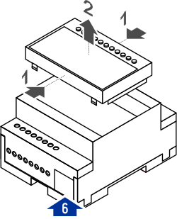 |
Remove front cover to access the inside:
Replace the front cover before to operate the unit. |
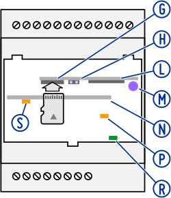 |
G Micro-SDTM card holder H Infrared receiver L WiFi / Bluetooth antenna M Infrared transmitter N Cellular modem WITH PLMN OPTION ONLY P Battery LED YELLOW WHILE CHARGING R Power supply LED GREEN WHEN DEVICE IS ON S PLMN status LED WITH PLMN OPTION ONLY |
Plan général
 |
|
| Negative • 01 | 13 • Main Power Supply |
| Analog Input 1 • 02 | 14 • Main Power Supply |
| Analog Input 2 • 03 | 15 • ⎯ |
| Analog Input 3 • 04 | 16 • Relays common |
| Analog Input 4 • 05 | 17 • Relay output 1 |
| Positive 3,3VDC • 06 | 18 • Relay output 2 |
| Digital Input 1 • 07 | 19 • Relay output 3 |
| Digital Input 2 • 08 | 20 • Relay output 4 |
| Digital Input 3 • 09 | |
| Digital Input 4 • 10 | |
| Digital Input 5 • 11 | |
| Digital Input 6 • 12 | |
| Regulated 3,3V – 50mAMAX available at terminal 06 respect to negative terminal 01 can be switched on / off. For battery equipped units such power supply is provided also when main power supply is missing. | |
Câblage des entrées digitales
| Up to 6 SPST contacts can be wired to terminals 07-12. Status is reported on LED indicators [F].
Internal power supply available at terminal 06. Debounce time setting for each input in the range 1 second to 18 hours. |
|
| INPUT voltage | 3 … 9 VDC |
| INPUT current | 2 mA @ 3,3V |
| output voltage | 3,3 VDC AT TERMINAL 06 |
 |
|
| Inputs can operate also as a pulse or time counter. SPST contacts, magnetic reeds, hall sensors or electronic switches can be used. | |
| PULSE WIDTH | > 20 ms |
| FREQUENCY | < 25 Hz |
 |
|
| A WIEGAND reader can be connected to digital inputs I1 (data 0, terminal 07) and I2 (data 1, terminal 08). Led indicators are illuminated when data line is connected. Negative (GND) to terminal 01. | |
When inputs are supplied by external source, negative is connected to terminal 01, voltage must be kept within 9 VDC.External power supply for inputs must meet SELV circuits requirements according to EN/IEC 62368. |
|
Câblage des entrées analogiques
|
Up to 4 analog signals can be connected at terminals 02-06 respect to negative terminal 01. Input mode and range can be selected by software for each input. Unreliable values returned for measures outside the input range. |
||
 |
Voltage source here is connected to analog input A2 (terminal 03) respect to negative (terminal 01). | |
| INPUT RANGE | 1 … 10 V | |
| INPUT MAX | 12 V | |
| RESOLUTION | 0,014 V | |
| ACCURACY | ± 2 % | |
| IMPEDANCE | 25 kohm | |
| NTC temperature sensor here is connected to analog input A4 (terminal 05) and powered by 3,3V internal power supply (terminal 06). | ||
| INPUT RANGE | -40 … 100 °C | |
| RESOLUTION | 0,1 °C | |
| ACCURACY | ± 2 °C | |
| NTC |
10 kohm @ 25÷85°C B: 3435 @ 25÷85°C RSR001 103AT/11 |
|
 |
Current source here is connected to analog input A2 (terminal 03) respect to negative (terminal 01). | |
| INPUT RANGE | 2 … 20 mA | |
| INPUT MAX | 24 mA | |
| VOLTAGE DROP | 2 V @ 20 mA | |
| RESOLUTION | 0,028 mA | |
| ACCURACY | ± 2 % | |
| IMPEDANCE | 100 ohm | |
|
10 komh potentiometer is connected to analog input A4 (terminal 05) to measure the voltage corresponding to cursor position between 1 and 3,3V (terminal 06). 4,7 kohm resistor introduces 1V offset to keep the signal within the reliable input range. |
||
| Measuring unit and returned value for FULL SCALE reading can be set for any input. The measure corresponding to ZERO can be set (i.e.: for 4÷20mA inputs set zero to 4, for 2÷10V input set zero to 2). | ||
| FULL SCALE VALUE | -1000000 … +1000000 | |
| ZERO | 0 … 21 | |
| UNIT | any text | |
| SHILEDED CABLE COULD BE USED FOR LONG LINES: SHIELD CONNECTED TO NEGATIVE TERMINAL 01 ONLY, OTHER END MUST BE LEFT UNCONNECTED | ||
Câblage des sorties
|
Up to 4 SPST relay contacts are available for process or appliance control at terminal 17-20. Status is reported on LED indicators [D]. Common return at terminal 16. |
|
| RETED CURRENT |
3 A cosφ=1 1 A cosφ=0,6 |
| RATED VOLTAGE | 250 VAC |
| BREAKING voltage | 277 VAC |
| MAX BREAKING CAPACITY | 750 VA |
| INSULATION TO IEC60664 |
Voltage rating 277 V Category as basic insulation III Category as reinforced insulation II surge voltage coil-contacts 5000 VRMS |
| DIELECTRIC STRENGTH |
coil-contacts 3000 VRMS open contacts 750 VRMS |
 |
|
| TO PREVENT RELAY CONTACTS FROM DAMAGING, AN EXTERNAL PROTECTION SHOULD BE PROVIDED (FUSE OR SIMILAR), ACCORDING TO THE RELAY BREAKING CAPACITY. | |